SuperTrack Starting Gate Detail
Here are some pictures of the Start Gate along with explanations of the relevant parts and their functions. Note: all pictures are viewed from the underside of the assembly.
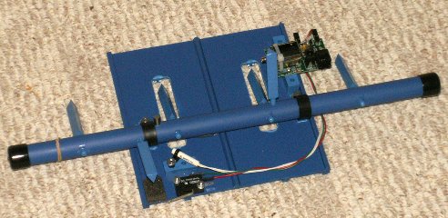
The first picture shows the gate in the open (cars released) condition. There are six blue paddles visible. Four of them (6 in a six lane assembly) hold the cars back. In the upper right is the latch solenoid which is engaged by the fifth paddle standing straight up. In the lower left is the damping sponge that absorbs the final stop impact from the sixth paddle just above it.
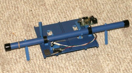
To the right is the same view but with the gate in the closed (cars held) condition. The four car paddles can now be seen to have a flat face that holds the cars. The latch paddle is now engaging the solenoid plunger. And, the damper paddle is now far away from the damping sponge.
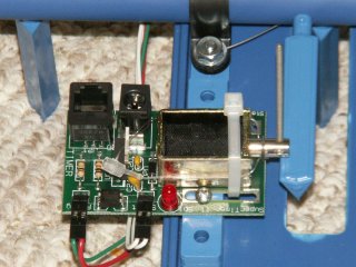
Here is a view of the latch mechanism with the gate in the closed condition that includes close up views of the paddles. Note that one edge of the paddle triangle is sharp and two are rounded. The flat surface with rounded edges always points toward the cars when it's a car paddle.
The thin clear nylon cord taped to the solenoid and threaded through the solenoid plunger serves two purposes. First, it keeps the plunger from coming out (and getting LOST!) during the time the gate is open or in storage. Second, because the nylon cord is taped to the sides of the solenoid, the cord serves as a weak return spring for the plunger. This spring pushes the plunger back out whenever the solenoid energy is released. When the gate is rotated from the open position, the slope of the latch paddle pushes the solenoid plunger in until the paddle goes past the plunger. Then the spring pushes the plunger back out, latching the gate closed. The long thin split pin which is perpendicular to the plunger is a handle provided for manual operation of the plunger. It is provided for SuperTimer II users with a conventional track and/or their own unique starting mechanism and is rarely used with SuperTrack.
Two pairs of wires attached to the solenoid board come from the switches described in the next pictures. The Red Led next to the solenoid is lit whenever the solenoid is energized if the two wires are connected as shown. For more recent boards, where the wires connect immediately adjacent to each other, the Red Led (a very small surface mount device) is always on and goes off whenever the solenoid is energized.
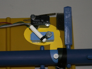
In the first picture, the black highlighted switch is the "Ready" switch. When the cars are ready, this switch is pressed and HELD signaling SuperTimer II that a race is about to start. The Ready switch must be held until the cars leave the starting gate. At that time the Start sensor (described below) starts the timing sequence. The Ready switch enables the Red Button in the center of SuperTimer II (white box, yellow label). Typically the racer in Lane 1 presses the Red Button to start the race.
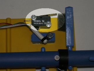
The paddle engaging the sponge is the damping paddle. The black nylon clamps must be perpendicular to the starting bar. The starting bar should rotate up and down freely. Side to side movement of the starting bar (undesired) is restricted by the damping paddle and the magnet (silver rod perpendicular to damping paddle) acting as thrust bearings in conjunction with the black nylon clamp. Be sure the black nylon clamp hits the ROUND portion of the damping paddle. The magnet should engage the black nylon clamp on only one end, the other end should be flush with the rotating bar.
In the second picture the highlight is of the Magnetic Start Sensor and its magnet. The magnet in the position shown provides essentially no magnetic field to the magnetic sensor. When the starting bar rotates to the closed position, the end of the magnet which is flush with the starting bar approaches the sensor closing an internal contact. As shipped, there is considerable distance in the gate closed condition between the magnet and the sensor. This is correct. The sensor should be physically aligned as shown. Electrically it will open/close around the half travel point of the rotating starting bar. If the magnet is too close to the sensor, the sensor will not open when the gate does. If necessary, the trip point can be adjusted by sliding the Start Sensor forward or back in its black tie wrap holder. You can test the trip point simply by NOT pressing the Ready switch and then raising/lowering the start gate slowly by hand. You should hear the trip point by listening for the speakers to say, "Please close the start gate" (indicating it is open) or by going silent (indicating that it is closed).
If you have an older model (with lots of Start Sensor mounting screw threads showing above the nut) you can make the adjustment much easier to perform by adding an 8-32 nut between the black tie wrap and the blue spacer. This nut raises the sensor closer to the mid-point of the magnet in the open position creating greater 'nulling' of the two poles.
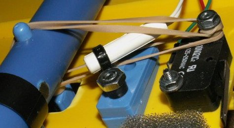
Partially visible in the second picture at the top of the page is a custom expansion spring which became available in September, 2008. Older models used rubber bands as described here. The larger rubber band (industry standard #33) acts to pull the gate down quickly when the solenoid is energized (latch released). The smaller rubber band (industry standard #16) acts to slow the gate down near the end of travel thus reducing, although not eliminating, the need for the damping paddle. This damping rubber band should be nearly loose when the gate is up. Both rubber bands are hooked on the Lane 2 Paddle base. The smaller rubber band hooks on the Ready switch mounting screw. The large rubber band has 1.5 turns on the Ready switch screw. More turns will pull the gate down faster but may cause the damping paddle to bang the foam pad. Fewer turns may not pull the pegs below the track. Spare rubber bands are shipped with SuperTrack. The industry standard numbers are provided in case you lose them and are available at most office supply stores.
Owners of older SuperTracks that still use rubber bands are encouraged to upgrade. If you are unable to upgrade, here's a picture of how they should be arranged.
![[SuperTrack]](/track/pinewood_derby_track_tr1c.jpg)
![[SuperTimer II]](/ssi/pinewood_derby_timer_pw.gif)
![[College]](/ssi/college.gif)
![[home]](/ssi/pinewood_derby_home.gif)