Space
Derby – User Created

Several users have asked us if we
support the Space Derby. Our first timers did and frankly, the market
was just not there. However, we did develop a finish line sensor
system which can be adapted to the current SuperTimer II. We do offer
a second finish line circuit board to make the changeover easier, we
do not offer a kit of parts since they are commonly available in your
local hardware store.
Making
the Switches
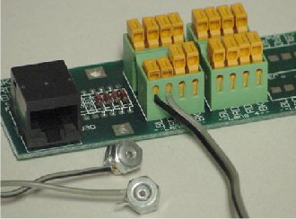
For each lane use two 'blind' or 'pop'
rivets with a diameter of 1/8” and a length of 1/4” (grip range
of 1/16” to 1/8”) along with two #8 machine nuts and several feet
of #24 speaker wire or similar. Be sure the wire you use will fit in
the Orange/Green connector of the finish line circuit board. The
wire will need to be long enough to reach from your finish line to
slightly beyond your final support.
Slide a nut on the rivet, then wrap a
stripped wire lead around the rivet, then slide on the other nut (The
nuts act like thick flat washers to use up all the length of the pop
rivet. A very small tie wrap can be used in place of the first nut to
act as a local strain relief.) Pop the rivet. Use the broken mandrel
backwards to punch out the remaining broken end if necessary creating
a smooth clear inner channel. Do this for both wires for each lane.
Be sure the inside is smooth and straight. Place both rivets with
their wide ends facing each other on the 'carrying line' for one
Space Derby Lane.
Feed the wire toward the end of the
track and rotate the rivets about the carrying line so that you get
about 1 twist per foot to support the wire on the carrying line.
Twisting the wire on the line will also keep it out of the way of the
propeller. Place the rivets at the finish line about an 1/8” apart.
The Space Derby Rocket Carrier will hit the rivets forcing them
together and making the momentary connection required by SuperTimer
II. Repeat for other lanes.
Wiring
the Switches.
The wiring from the switches will need
to be connected to the finish line circuit board of SuperTimer II.
There are two options. The tight budget option uses the existing
finish line board - wiring and un-wiring for each event. This is not
recommended but will work. A second board can be purchased which will
make the changeover significantly easier although adding some
expense. Creative persons may find alternate means. See the P.S.
below.
From each lane switch connect one wire
to the appropriate lane's terminal marked Blue and the other wire to
either terminal marked Red for that same lane. It doesn't matter
which terminal goes to which wire. If the wire gage is very small, it
will help to bend a 1/4” of the wire backwards and crimp it tightly
thus increasing its effective gage before inserting it into the punch
down connector.
P.S.
Creative and hopefully Electronic
Technical persons should read this paragraph before proceeding with
alternate connection methods. The normal Pinewood Derby Lane
switches are voltage generators connected from the micro-controller
input for each lane (Red wire) to ground (Black wire). The Pinewood
Derby Lane LEDs that flash during the winner announcement are
connected from the Red wire (nominal lane input) to the Blue wire
switched common. During a Race, the Blue wire is held high (reverse
biasing the LEDS). After the race the Blue wire is held low and the
micro-controller input becomes an output flashing the appropriate
LED. {Curiously, the voltage applied across the piezo Pinewood Derby
Sensor in this instance makes it effectively but very inefficiently a
speaker.} The Space Derby switches thus use the Blue 'led switched
ground' during its high state to emulate the voltage generating
Pinewood Derby Sensors. An attempt to wire both systems
simultaneously will thus cause the LEDS not to operate and the
Pinewood Derby race to end prematurely if the Space Derby switches
are inadvertently closed.
Starting Gate
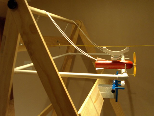
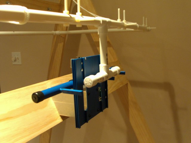
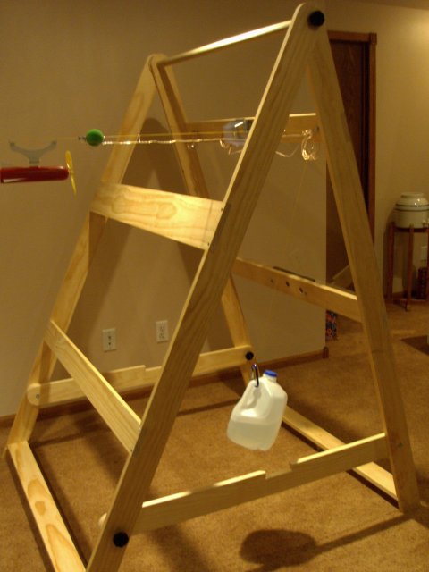
The following pictures have been provided by of Steve Zirtzman of the Hawkeye Area Council in Cedar Rapids, Iowa. These are from his prototype Space Derby Track taken prior to some implemented and planned changes some of which are detailed below the pictures. This design employs an extremely creative use of the SuperTrack starting gate to start the Space Derby. While it's not practical to re-use the Finish line assembly from SuperTrack, the re-use of the Starting gate assembly provides both a reliable start mechanism and avoids the extra expense ($65) of a second solenoid board.


Some Suggested Changes
- Redesign the stand so that the front legs are inside the rear legs. This has several advantages as will become clear below.
- Pivot the PVC start frame on the front legs instead of the rear legs as shown. This will allow the back of the start frame to counterbalance the front reducing the load on the SuperTrack start gate. The shorter length from pivot to start will also improve pin clearance slightly.
- Move the white cords, which limit gate travel, from the front of the PVC frame to the back of the frame for a neater and simpler approach. A single cord in the middle should suffice. Releasing this cord will allow the entire stand to fold up as before.

![[SuperTrack]](/track/pinewood_derby_track_tr1c.jpg)
![[SuperTimer II]](/ssi/pinewood_derby_timer_pw.gif)
![[College]](/ssi/college.gif)
![[home]](/ssi/pinewood_derby_home.gif)


