THIS INFORMATION APPLIES ONLY TO SUPERTIMER II REVISION 1.XX HARDWARE
HARDWARE WAS CHANGED AND STATIC SENSITIVITY ELIMINATED IN LATER HARDWARE REVISIONS

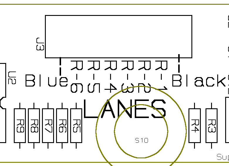
The above is a mechanical layout drawing of a section of the SuperTimer II circuit board. If you are having trouble with one or more Lane Sensors or Lane Leds you can use the above picture and a continuity tester to help resolve the problem. The Leds have fully insulated leads so getting access to them will be difficult and tracing the problem will require some deduction. On the other hand, the Sensors have an uninsulated section that can be accessed simply by lifting them up slightly from their slot in the track. Looking at the above diagram, the lower pin of Resistors R3-R4-R5-R6-R7 and R8 are all connected together and should also show continuity to all Black wires on All Sensors. The Red wire on the Sensor for Lane 1 connects to the top of R3; Lane 2 the top of R4; Lane 3 the top of R5; etc. The Blue lead connects to all Blue Led leads and to the top of R9. 'Continuity' means very low resistance (it's a piece of Wire). The power should be off when making these tests to insure that voltages on the board don't affect your readings.
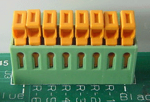
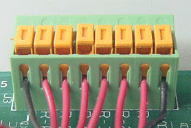
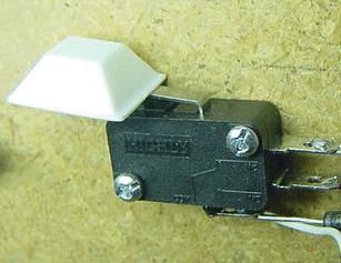
Included below are three pictures: The Orange/Green connector BEFORE wires are inserted. The Orange/Green Connector AFTER wires are inserted. The 'READY' switch with a self-stick foot attached to lessen the sensitivity to a static spark resetting SuperTimer II.


Copyright © 2003 SuperTimer